O-RAN 7.2 RU Guide
Overview
srsRAN Project supports both split 7.2 and split 8 fronthaul interfaces to Radio Units (RUs). This tutorial outlines the general steps required to interface an RU with the srsRAN CU/DU via split 7.2. For more detailed instructions on specific O-RUs select an RU from this list.
Split 7.2 is an open specification published by the O-RAN Alliance aiming to ensure interoperability between different DU and RU solutions.
The split 7.2 interface is supported in srsRAN through the Open Fronthaul (OFH) Library. Developed by the SRS team, OFH is an open-source, portable library with minimal 3rd-party dependencies. It has been designed to minimize the integration and configuration burden associated with using srsRAN with 3rd-party O-RUs.
Setup Considerations
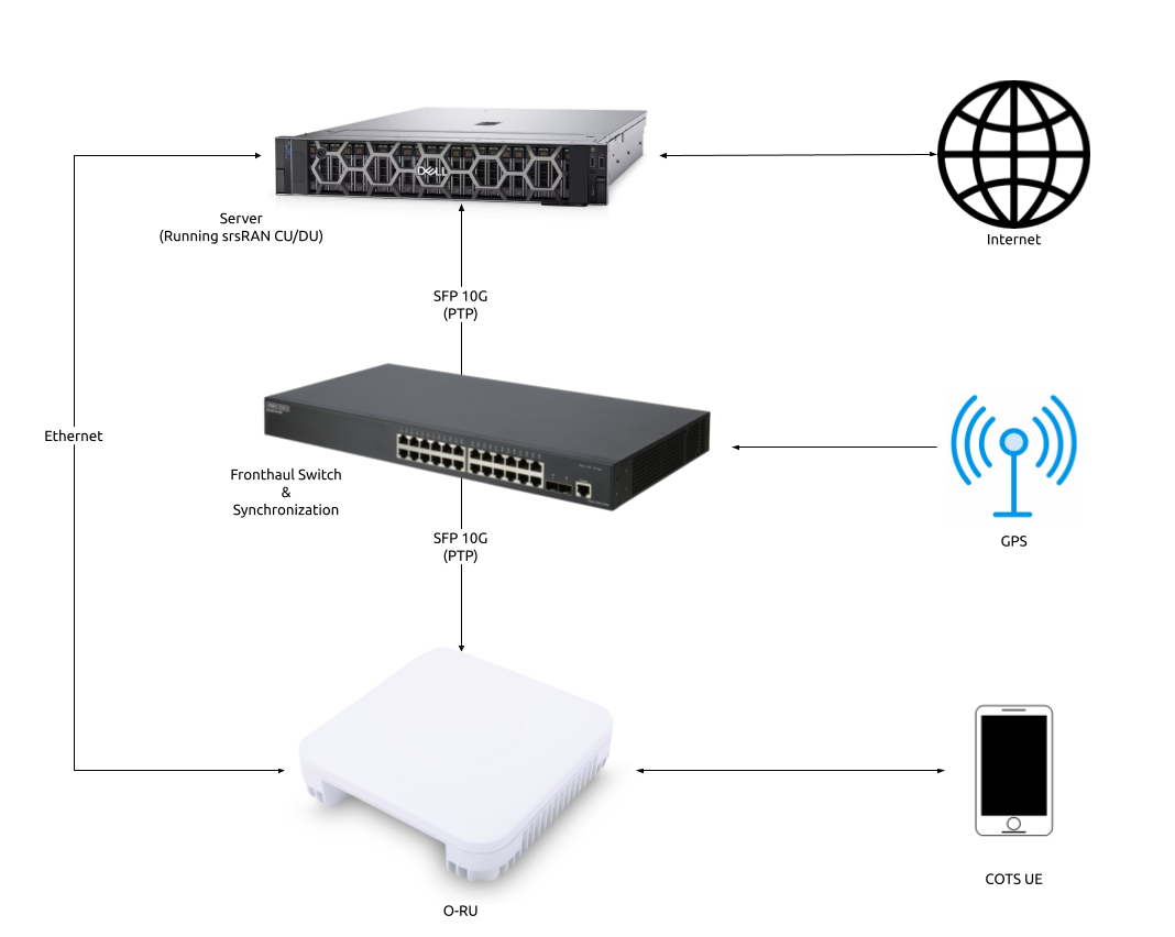
This tutorial uses the following hardware:
Server (Running srsRAN Project CU/DU)
CPU: AMD Ryzen 7 5700G
MEM: 64GB
NIC: Intel Corporation 82599ES 10-Gigabit
OS: Ubuntu 22.04 (5.15.0-1037-realtime)
Fronthaul switch & synchronization
RU
COTS UE (OnePlus 9)
With the following software:
CU/DU
The CU/DU is provided by the srsRAN Project. The Open Fronthaul (OFH) Library provides the necessary interface between the DU and the RU. The DU is connected to the fronthaul switch via SFP+ fiber cable.
RU
Users should chose the RU that best suits their usecase and specific requirements. There are various O-RUs available with specific implementations for indoor and outdoor use, various price points, and various hardware capabilities. A list of tested O-RUs can be found here, along with details on using them with srsRAN Project.
For all set-ups the RU should be connected to the fronthaul switch via SFP+ fiber cable through the main fronthaul interface.
5G Core
For this example we use the Open5GS 5G Core.
Open5GS is a C-language open-source implementation for 5G Core and EPC. The following links will provide you with the information needed to download and setup Open5GS so that it is ready to use with srsRAN:
Synchronization
The split 7.2 interface requires tight timing synchronization between the DU and RU. O-RAN WG 4 has defined various synchronization methods for use with Open Fronthaul. These are outlined in O-RAN.WG4.CUS.0-R003-v11.00 Section 11.
In this setup we use LLS-C3. The LLS-C3 configuration enables the distribution of network timing between central sites and remote sites from PRTC/T-GM to RU. In simpler terms, it allows the synchronization of one or more PRTC/T-GM devices (serving as PTP master) in the fronthaul network to transmit network timing signals to DU and RU components as seen in the figure above. In our setup the fronthaul switch is acting as the PTP grandmaster (which is synchronized via GPS), providing timing to the RU and the DU. These are connected to the SFP+ 10G ports on the switch via Ethernet.
Note
The OFH library supports all of the defined clock model and synchronization topologies defined by O-RAN WG4. The use of LLS-C3 is specific to this example.
Switch
The chosen switch should be a timing-aware O-RAN switch & PTP grandmaster. This is used to provide both clocking and timing synchronization to both the DU and RU.
Configuration
Switch
Refer to the specific Switch documentation to correctly configure it. Specifically any timing and routing options that may need to be configured.
We recommend using the manufacturers documentation as well as the specific switch guide from SRS if it is available in the Integration Guide.
CU/DU
NIC configuration
The DU machine should have jumbo frames enabled in the NIC and the PTP process should be checked to make sure it is synchronized correctly.
To set the jumbo frames in the NIC use the following command for a temporary configuration:
ifconfig <eth0> mtu 9600 up
Where eth0 is the ethernet port for the SFP+ fiber cable that connects the DU to the fronthaul switch.
PTP configuration
PTP is used to synchronize the DU with the fronthaul switch. The PTP process should be running on the DU and the PTP sync should be checked to ensure it is synchronized correctly. ptp4l and phc2sys are the two main components of the PTP synchronization with linuxptp. To avoid any issues with the PTP, it is recommended to disable the Network Time Protocol (NTP) on the DU. Use the following command to disable NTP on Ubuntu 22.04:
sudo timedatectl set-ntp false
We have created an example configuration file for G.8275.1 Multicast PTP profile for LinuxPTP version 4. It can be downloaded here.
Install the LinuxPTP v4 using the following command:
git clone http://git.code.sf.net/p/linuxptp/code linuxptp
cd linuxptp/
git checkout v4.2
make
sudo make install
Run ptp4l using the following command:
sudo ptp4l -2 -i enp1s0f0 -f ./configs/default.cfg -m
You should then see the following output:
ptp4l[4321.966]: rms    6 max   14 freq -25784 +/-   9 delay   172 +/-   1
ptp4l[4323.091]: rms    5 max   10 freq -25778 +/-   8 delay   170 +/-   1
ptp4l[4324.216]: rms    6 max   11 freq -25781 +/-   9 delay   169 +/-   1
ptp4l[4325.341]: rms    5 max   10 freq -25783 +/-   8 delay   170 +/-   1
In the above output, the rms value can be used to determine if the PTP sync is correct, for this we look for a value < 10.
Next, run:
sudo phc2sys -s enp1s0f0 -w -m -R 8 -f ./configs/default.cfg
You should then see the following output:
phc2sys[4348.303]: CLOCK_REALTIME phc offset       -25 s2 freq   +8026 delay   1467
phc2sys[4348.428]: CLOCK_REALTIME phc offset       -11 s2 freq   +8033 delay   1466
phc2sys[4348.553]: CLOCK_REALTIME phc offset       -25 s2 freq   +8016 delay   1396
phc2sys[4348.678]: CLOCK_REALTIME phc offset        -5 s2 freq   +8028 delay   1397
The first value here is used to determine if the PTP sync is correct, for this we look for a value in the range of -100 to 100.
In both of the above commands enp1s0f0 is the network interface on our DU that gets the PTP sync.
Enabling PTP with DPDK
If you are using PTP and OFH with DPDK on the same interface, you will need to use virtual functions (VFs) to ensure that the PTP sync is correctly passed to the relevant components.
First, identify the network port you want to use for PTP and OFH. You can use the following command to list the available network ports:
dpdk-devbind.py -s
You will see the following output or similar:
Network devices using using kernel driver
=============================================
0000:51:00.0 'Ethernet Controller E810-C for SFP 1593' if=enp81s0f0 drv=ice unused=vfio-pci *Active*
0000:51:00.1 'Ethernet Controller E810-C for SFP 1593' if=enp81s0f1 drv=ice unused=vfio-pci *Active*
0000:51:00.2 'Ethernet Controller E810-C for SFP 1593' if=enp81s0f2 drv=ice unused=vfio-pci
0000:51:00.3 'Ethernet Controller E810-C for SFP 1593' if=enp81s0f3 drv=ice unused=vfio-pci
In the above output, enp81s0f0 is the network port we want to use for PTP and OFH.
Next, you will need to create the VF, you can do this by running the following commands. Remember to replace <INTERFACE NAME> with the name of your network interface (e.g., enp81s0f0):
# Remove old VFs
echo 0 | /sys/class/net/<INTERFACE NAME>/device/sriov_numvfs

# Create new VF
echo 1 | /sys/class/net/<INTERFACE NAME>/device/sriov_numvfs

# Set the MAC address for the VF
sudo ip link set <INTERFACE NAME> vf 0 mac 00:33:22:33:00:11 spoofchk off
Now, you can verify that the VF as been created by running the following command:
dpdk-devbind.py -s
You should see the following output or similar:
Network devices using using kernel driver
=============================================
0000:51:00.0 'Ethernet Controller E810-C for SFP 1593' if=enp81s0f0 drv=ice unused=vfio-pci *Active*
0000:51:01.0 'Ethernet Adaptive Virtual Function 1889' drv=iavf unused=vfio-pci
0000:51:00.1 'Ethernet Controller E810-C for SFP 1593' if=enp81s0f1 drv=ice unused=vfio-pci *Active*
0000:51:00.2 'Ethernet Controller E810-C for SFP 1593' if=enp81s0f2 drv=ice unused=vfio-pci
0000:51:00.3 'Ethernet Controller E810-C for SFP 1593' if=enp81s0f3 drv=ice unused=vfio-pci
In the above example, we can see that the VF has been created and is using the iavf driver in the line Adaptive Virtual Function. Note, this is only for the Intel E810 NIC, other NICs may have different drivers.
Next, you will need to bind the VF to the vfio-pci driver, you can do this by running the following command. Before running this command, make sure that vfio-pci is enabled, see the DPDK Guide for more information on how to enable it.
sudo dpdk-devbind.py --bind=vfio-pci 0000:51:01.0
Finally, verify the binding by running the following command:
dpdk-devbind.py -s
You should see the following output or similar:
Network devices using DPDK-compatible driver
============================================
0000:51:01.0 'Ethernet Adaptive Virtual Function 1889' drv=vfio-pci unused=iavf

Network devices using kernel driver
===================================
0000:51:00.0 'Ethernet Controller E810-C for SFP 1593' if=enp81s0f0 drv=ice unused=vfio-pci *Active*
0000:51:00.1 'Ethernet Controller E810-C for SFP 1593' if=enp81s0f1 drv=ice unused=vfio-pci *Active*
0000:51:00.2 'Ethernet Controller E810-C for SFP 1593' if=enp81s0f2 drv=ice unused=vfio-pci
0000:51:00.3 'Ethernet Controller E810-C for SFP 1593' if=enp81s0f3 drv=ice unused=vfio-pci
srsRAN configuration
Sample configuration files for the CU/DU can be found in the configs folder of the srsRAN source files. There is an associated configuration file for each of the tested RUs.
The main configuration steps for the CU/DU occur in the ru_ofh field. Here the CU/DU is configured to match the capabilities of the RU being used. All parameters should be configured specifically for each RU.
See the specific RU guides in the Integration Guide for more information on configuring the CU/DU.
RU
Refer to the specific RU documentation to correctly configure the RU. Ensure the RU is running before trying to make any configuration changes.
We recommend using the manufacturers documentation as well as the specific RU guide from SRS if it is available in the Integration Guide.
Core
For this setup Open5GS is used as the core, it is running in a docker.
The Open5GS 5G Core Quickstart Guide provides a comprehensive overview of how to configure Open5GS to run as a 5G Core.
To configure the core correctly the following steps need to be taken:
Configure the core to connect to the gNB, ensuring the correct AMF address for both.
Configure the PLMN and TAC values so that they are the same as those present in the gNB configuration.
Register the ISIM credentials of the UE to the list of subscribers through the Open5GS WebUI.
Initializing the Network
RU
To bring up the RU simply boot it and ensure it is running correctly before attempting to connect the DU. Check for RU synchronization and that the PTP process is running correctly.
These exact steps will vary depend on the RU being used.
CU/DU
Before running the CU/DU, make sure you have used the commands outlined in the configuration section above to confirm the PTP sync between the DU and the fronthaul switch.
We can now run the CU/DU. First, navigate to srsRAN_Project/build/apps/gnb, and then run the gNB with the following command:
sudo ./gnb -c <RU_CONFIG>
Where <RU_CONFIG> is the configuration file associated with the RU being used.
If the DU connects to the RU successfully, you will see the following output or similar:
--== srsRAN gNB (commit ) ==--

Connecting to AMF on 10.53.1.2:38412
Initializing Open Fronthaul Interface with ul_comp=[BFP,9], dl_comp=[BFP,9], prach_cp_enabled=false, downlink_broadcast=true.
Operating a 20MHz cell over a RU with instantaneous bandwidth of 100MHz.
Warning: Configured PRACH occasion collides with PUCCH RBs ([0..1) intersects [0..3)). Some interference between PUCCH and PRACH is expected.
Warning: Configured PRACH occasion collides with PUCCH RBs ([0..1) intersects [0..3)). Some interference between PUCCH and PRACH is expected.
Cell pci=1, bw=20 MHz, dl_arfcn=634548 (n78), dl_freq=3518.22 MHz, dl_ssb_arfcn=634464, ul_freq=3518.22 MHz

==== gNodeB started ===
Type <t> to view trace
Connecting to the Network
The following sections will outline two different approaches for connecting to the network. The first will show how to connect to the network using a COTS UE, the second will show how to connect using the AmariUE UE emulator from Amarisoft.
COTS UE
For full details on configuring and connecting a COTS UE to srsRAN Project see this tutorial.
For this setup a OnePlus 9 5G UE was used to connect to the network. The set-up and configuration of the device is the same as in the above tutorial.
AmariUE
Additionally, third party UEs, such as AmariUE can be used to connect to the network.
For full details on configuring and connecting AmariUE to srsRAN Project see this tutorial.
Sending Traffic
Once connected to the network you can use iPerf to generate traffic. The following console trace was taken from the gNB during bi-directional testing:
          -------------DL----------------|------------------UL--------------------
pci rnti  cqi  mcs  brate   ok  nok  (%) | pusch  mcs  brate   ok  nok  (%)    bsr
  1 4601   15   28    38M 1200    0   0% |  17.8   26    15M  493  107  17%   300k
  1 4601   15   28    38M 1186   14   1% |  17.7   26    14M  488  112  18%   300k
  1 4601   15   28    38M 1196    4   0% |  17.8   26    15M  506   94  15%   300k
  1 4601   15   28    38M 1200    0   0% |  17.8   26    15M  501   99  16%   300k
  1 4601   15   28    38M 1200    0   0% |  17.9   26    15M  498  102  17%   300k
  1 4601   15   28    38M 1200    0   0% |  17.9   26    15M  497  103  17%   300k
  1 4601   15   28    38M 1198    2   0% |  17.8   26    15M  497  103  17%   300k
  1 4601   15   28    38M 1194    6   0% |  17.8   26    15M  495  105  17%   300k
  1 4601   15   28    38M 1195    5   0% |  17.8   26    15M  510   89  14%   300k
  1 4601   15   28    38M 1200    0   0% |  17.8   26    15M  503   98  16%   300k
  1 4601   15   28    38M 1200    0   0% |  17.8   26    15M  495  105  17%   300k
Integration Guide
The Integration Guide aims to show the specific steps needed to successfully integrate COTS O-RUs and switches with the srsRAN CU/DU for use in an O-RAN split 7.2 compliant network. All of the hardware items listed here have been tested in-house.