5G NSA COTS UE
Tip
The srsENB supports prototype 5G features for both NSA and SA modes of operation however, these features are no longer under active development. Instead we recommend the srsRAN Project, our ORAN-native 5G CU/DU solution.
Warning
Operating a private 5G NSA network on cellular frequency bands may be tightly regulated in your jurisdiction. Seek the approval of your telecommunications regulator before doing so.
Introduction
This application note shows how to create your own 5G NSA network using srsENB, srsEPC and a 5G capable COTS UE. There are two options for network setup when connecting a COTS UE: The network can be left as is, and the UE can communicate locally within the network, or the EPC can be connected to the internet through the P-GW, allowing the UE to access the internet for web-browsing, email etc.
Network & Hardware Overview
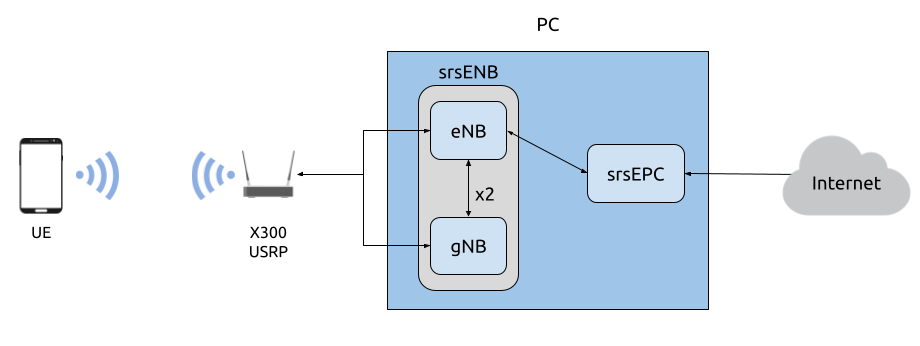
Simplified network architecture
Setting up a 5G NSA network and connecting a 5G COTS UE requires the following:
PC with a Linux based OS, with srsRAN 4G installed and built
A dual channel RF-frontend with independent RF chains
A 5G NSA-capable UE
USIM/ SIM card (This must be a test card or a programmable card, with known keys)
For this implementation the following equipment is used:
Desktop computer (minimum 6th Gen i7 or similar) with 10GigE NIC
X300 USRP
OnePlus Nord 5G with a Sysmocom USIM
UE Considerations
One of the current limitations of srsRAN 4G is that both LTE and NR carrier have to use the same subcarrier spacing (SCS) of 15 kHz. Unfortunately, this limits the band combinations that can be used with COTS phones, as not all combinations are possible with every baseband chip.
For example, NR band n78 that is used in most European deployments to date (using 30 kHz SCS), in theory, also supports 15 kHz SCS. However, all phones we’ve tried with cannot support 15 kHz on this band. Check the supported band combinations for your handset using this webpage.
As a consequence, we suggest using FDD bands for both LTE and NR carrier, such as band 20 for LTE and band n3 for NR. Both bands are supported by the OnePlus 5G Nord used in this appnote.
Besides the restrictions originating from the baseband hardware there are a few other pitfalls that may or may not allow a phone to connect to a 5G network.
Many 5G handsets may contain a carrier policy file that may limit 5G capabilities of the phone based on the PLMN of the USIM (first 6 digits of IMSI). Carrier policy files typically don’t include test network PLMNs, so setting a test PLMN may result in 5G being disabled. If possible, using a shielded box and configuring the network with a commercial carrier PLMN may avoid policy file issues.
On some handsets, when using a test USIM, you may need to activate 5G NR using
*#*#4636#*#*.If your handset supports “Smart 5G”, disable this option as it may force the handset to 4G and activate roaming.
Dependencies
RF Driver
We’ve only tested NSA mode with Ettus Research devices using UHD. For this appnote we use the USRP X310 with UHD version v3.15.
srsRAN 4G
If you have not already done so, install the latest version of srsRAN 4G and dependencies. This is outlined in the installation guide.
Note
If you install or update your driver after installing srsRAN 4G, you will have to re-build srsRAN 4G.
Checking Drivers
To check that your RF driver has been picked up when running cmake .. during the build process, you can run:
grep <driver> srsRAN_4G/build/CMakeCache.txt
If you are using UHD as your driver, you should see the following output if srsRAN 4G has successfully detected it when cmake .. was run:
$ grep UHD -m 4 CMakeCache.txt

//Enable UHD
ENABLE_UHD:BOOL=ON
UHD_INCLUDE_DIRS:PATH=/usr/local/include
UHD_LIBRARIES:FILEPATH=/usr/local/lib/libuhd.so
Configuration
The network will have to be configured to support the NSA network and to work with a COTS UE. The following srsRAN 4G configuration files will need to be updated:
The enb.conf and epc.conf files will need to be edited such that the MCC & MNC values match those of the USIM. The rr.conf needs to be updated to add the NR cell. The user_db.csv file needs to be updated so that it contains the credentials associated with the USIM card being used in the UE.
An APN will also need to be added to the COTS UE to allow it to access the internet. This is reflected in the EPC config file.
The configuration files used for this example set-up are attached above for reference. Users may need to edit the relevant fields so that their specific COTS UE will be supported by the network.
Add APN to COTS UE
To add an APN to the UE, navigate to the Network settings for the USIM being used. From here an APN can be added, usually under Access point names. Create a new APN with the name and APN test123, as shown below.
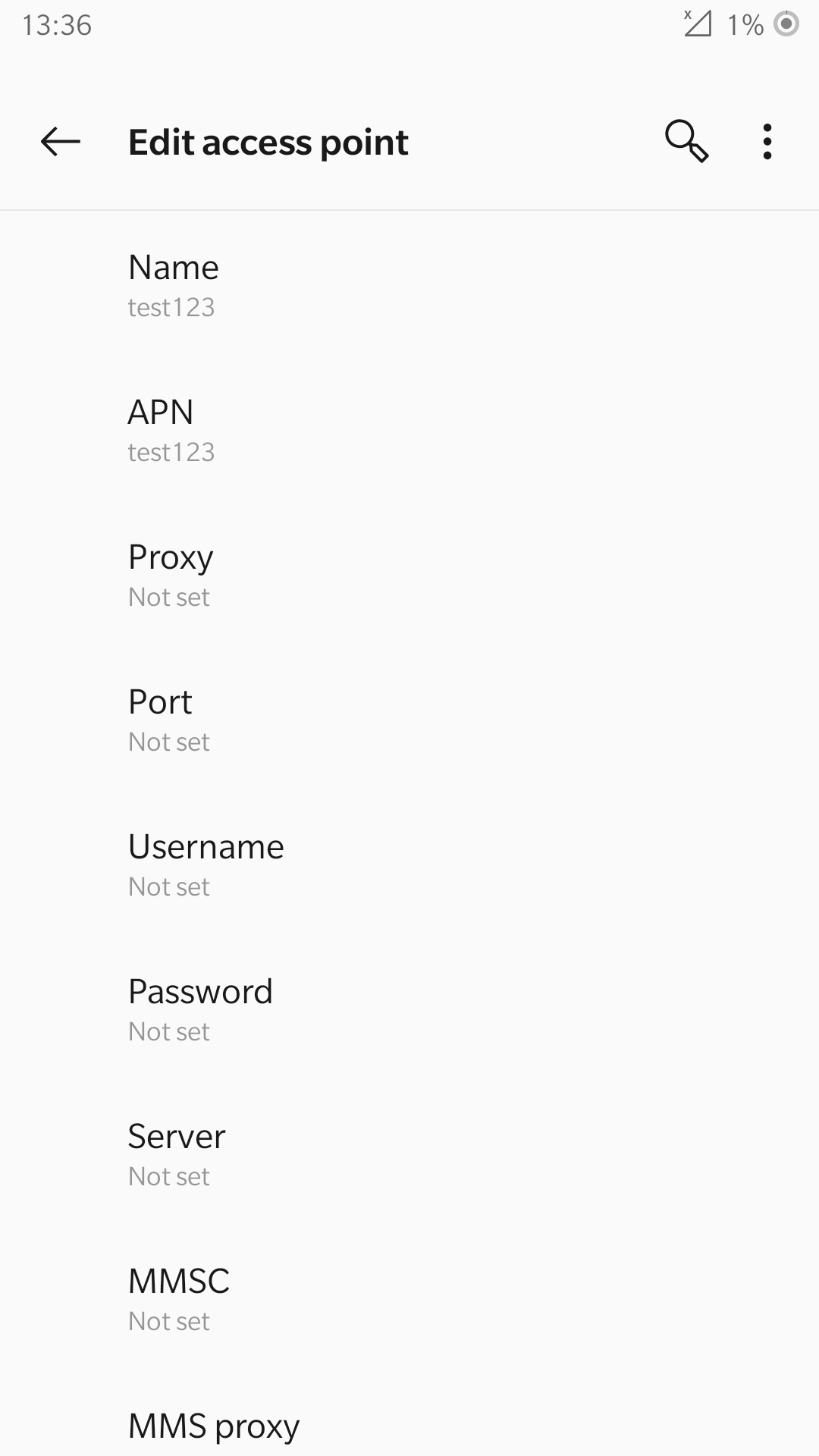
All other settings can be left on the default options. The name of the APN here does not actually matter, as long as the naming is consistent between the UE and the EPC.
srsENB
enb.conf
The MCC & MNC codes must be updated in the enb.conf to reflect the values used by the sim. These can be edited in the following section of the config file:
#####################################################################
[enb]
enb_id = 0x19B
mcc = 901
mnc = 70
mme_addr = 127.0.1.100
gtp_bind_addr = 127.0.1.1
s1c_bind_addr = 127.0.1.1
n_prb = 50
#tm = 4
#nof_ports = 2

#####################################################################
For the X310 we’ve seen acceptable results with the following device arguments:
[rf]
device_args=type=x300,clock=external,sampling_rate=11.52e6,lo_freq_offset_hz=11.52e6
The rest of the options can be left at the default values. They may be changed as needed, but further modification is not necessary to enable the successful connection of a COTS UE.
rr.conf
The main change to the rr.conf file is the addition of the NR cell to the cell list. This is added to the end of the file:
nr_cell_list =
(
   {
    rf_port = 1;
    cell_id = 0x02;
    tac = 0x0007;
    pci = 500;
    root_seq_idx = 204;

    // TDD:
    //dl_arfcn = 634240;
    //band = 78;

    // FDD:
    dl_arfcn = 368500;
    band = 3;
  }
);
Here we have added both the TDD and FDD configs. For this example we will be using the FDD configuration, so the TDD configuration is commented out. Check that the UE model supports the chosen bands.
Core
epc.conf
The EPC config file must be modified to reflect the MCC & MNC, as well as the APN being used by the UE:
#####################################################################
[mme]
mme_code = 0x1a
mme_group = 0x0001
tac = 0x0007
mcc = 901
mnc = 70
mme_bind_addr = 127.0.1.100
apn = test123
dns_addr = 8.8.8.8
encryption_algo = EEA0
integrity_algo = EIA1
paging_timer = 2

#####################################################################
user_db.csv
The following list describes the fields contained in the user_db.csv file. As standard, this file
will come with two dummy UEs entered into the CSV, these help to provide an example of how the file should be filled in.
Name: Any human readable value
Auth: Authentication algorithm (xor/ mil)
IMSI: UE’s IMSI value
Key: UE’s key, hex value
OP Type: Operator’s code type (OP/ OPc)
OP: OP/ OPc code, hex value
AMF: Authentication management field, hex value must be above 8000
SQN: UE’s Sequence number for freshness of the authentication
QCI: QoS Class Identifier for the UE’s default bearer
IP Alloc: IP allocation strategy for the SPGW
The AMF, SQN, QCI and IP Alloc fields can be populated with the following values for the COTS UE:
9000, 000000000000, 9, dynamic
This will result in a user_db.csv file that should look something like the following:
#
# .csv to store UE's information in HSS
# Kept in the following format: "Name,Auth,IMSI,Key,OP_Type,OP,AMF,SQN,QCI,IP_alloc"
#
# Name:     Human readable name to help distinguish UE's. Ignored by the HSS
# IMSI:     UE's IMSI value
# Auth:     Authentication algorithm used by the UE. Valid algorithms are XOR
#           (xor) and MILENAGE (mil)
# Key:      UE's key, where other keys are derived from. Stored in hexadecimal
# OP_Type:  Operator's code type, either OP or OPc
# OP/OPc:   Operator Code/Cyphered Operator Code, stored in hexadecimal
# AMF:      Authentication management field, stored in hexadecimal
# SQN:      UE's Sequence number for freshness of the authentication
# QCI:      QoS Class Identifier for the UE's default bearer.
# IP_alloc: IP allocation stratagy for the SPGW.
#           With 'dynamic' the SPGW will automatically allocate IPs
#           With a valid IPv4 (e.g. '172.16.0.2') the UE will have a statically assigned IP.
#
# Note: Lines starting by '#' are ignored and will be overwritten
COTS_UE,mil,901700000020936,4933f9c5a83e5718c52e54066dc78dcf,opc,fc632f97bd249ce0d16ba79e6505d300,9000,0000000060f8,9,dynamic
The auth, IMSI, key, OP Type and OP are values associated with the USIM being used. The values assigned to the AMF, SQN, QCI & IP Alloc are the default values above, which is explained further here in the EPC documentation. Ensure there is no white space between the values in each entry, as this will cause the file to be read incorrectly.
Masquerading Script
To allow UE to connect to the internet via the EPC, the pre-configured masquerading script must be run. This can be found in srsRAN_4G/srsepc.
The masquerading script enables IP forwarding and sets up Network Address Translation to pass traffic between the srsRAN 4G network and the external network. The script must be run each time the machine is re-booted, and can be done before or while the srsRAN 4G is running. The UE will not be able to communicate with the wider internet until this script has been run.
Before running the script it is important to identify the interface being used to connect your PC to the internet. The script requires this as an argument as shown below:
route
You will see an output similar to the following:
Kernel IP routing table
Destination     Gateway         Genmask         Flags Metric Ref    Use Iface
default         _gateway        0.0.0.0         UG    100    0        0 enxc03ebab05013
10.12.1.0       0.0.0.0         255.255.255.0   U     100    0        0 enxc03ebab05013
The interface (Iface) associated with the default destination is one which must be passed into the masq. script. In the above output that is the enxc03ebab05013 interface.
The masq. script can now be run from the follow folder: srsRAN_4G/srsEPC
sudo ./srsepc_if_masq.sh <interface>
If it has executed successfully you will see the following message:
Masquerading Interface <interface>
The configuration files, user DB and UE are now set up appropriately to allow the COTS UE to connect to the eNB and Core.
Connecting to the Network
The final step in connecting a COTS UE to srsRAN 4G is to first run the EPC and eNB, and then connect to that network from the UE. The following sections will outline how this is achieved.
Core
First run srsEPC:
sudo srsepc
The following output should be displayed on the console:
Built in Release mode using commit c892ae56b on branch master.

---  Software Radio Systems EPC  ---

Reading configuration file /etc/srsran_4G/epc.conf...
HSS Initialized.
MME S11 Initialized
MME GTP-C Initialized
MME Initialized. MCC: 0xf901, MNC: 0xff70
SPGW GTP-U Initialized.
SPGW S11 Initialized.
SP-GW Initialized.
srsENB
Now start srsENB:
sudo srsenb
The console should display the following or similar:
---  Software Radio Systems LTE eNodeB  ---

Opening 2 channels in RF device=uhd with args=type=x300,clock=external,sampling_rate=11.52e6,lo_freq_offset_hz=23.04e6,send_frame_size=8000,recv_frame_size=8000,num_send_frames=64,num_recv_frames=64,None
[INFO] [UHD] linux; GNU C++ version 9.3.1 20200408 (Red Hat 9.3.1-2); Boost_106900; UHD_3.15.0.0-62-g7a3f1516
[INFO] [LOGGING] Fastpath logging disabled at runtime.
Opening USRP channels=2, args: type=x300,lo_freq_offset_hz=23.04e6,send_frame_size=8000,recv_frame_size=8000,num_send_frames=64,num_recv_frames=64,None=,master_clock_rate=184.32e6
[INFO] [UHD RF] RF UHD Generic instance constructed
[INFO] [X300] X300 initialization sequence...
[INFO] [X300] Maximum frame size: 8000 bytes.
[INFO] [X300] Radio 1x clock: 184.32 MHz
[INFO] [0/DmaFIFO_0] Initializing block control (NOC ID: 0xF1F0D00000000000)
[INFO] [0/DmaFIFO_0] BIST passed (Throughput: 1315 MB/s)
[INFO] [0/DmaFIFO_0] BIST passed (Throughput: 1307 MB/s)
[INFO] [0/Radio_0] Initializing block control (NOC ID: 0x12AD100000000001)
[INFO] [0/Radio_1] Initializing block control (NOC ID: 0x12AD100000000001)
[INFO] [0/DDC_0] Initializing block control (NOC ID: 0xDDC0000000000000)
[INFO] [0/DDC_1] Initializing block control (NOC ID: 0xDDC0000000000000)
[INFO] [0/DUC_0] Initializing block control (NOC ID: 0xD0C0000000000000)
[INFO] [0/DUC_1] Initializing block control (NOC ID: 0xD0C0000000000000)
[INFO] [MULTI_USRP]     1) catch time transition at pps edge
[INFO] [MULTI_USRP]     2) set times next pps (synchronously)

==== eNodeB started ===
Type <t> to view trace
Setting frequency: DL=806.0 Mhz, UL=847.0 MHz for cc_idx=0 nof_prb=50
Setting frequency: DL=1842.5 Mhz, UL=1747.5 MHz for cc_idx=1 nof_prb=52
The EPC console should now print an update if the eNB has successfully connected to the core:
Received S1 Setup Request.
S1 Setup Request - eNB Name: srsenb01, eNB id: 0x19b
S1 Setup Request - MCC:901, MNC:70, PLMN: 651527
S1 Setup Request - TAC 0, B-PLMN 0
S1 Setup Request - Paging DRX v128
Sending S1 Setup Response
The network is now ready for the COTS UE to connect.
UE
You can now connect the UE to the network by taking the following steps:
Open the Settings menu and navigate to the Sim & Network options
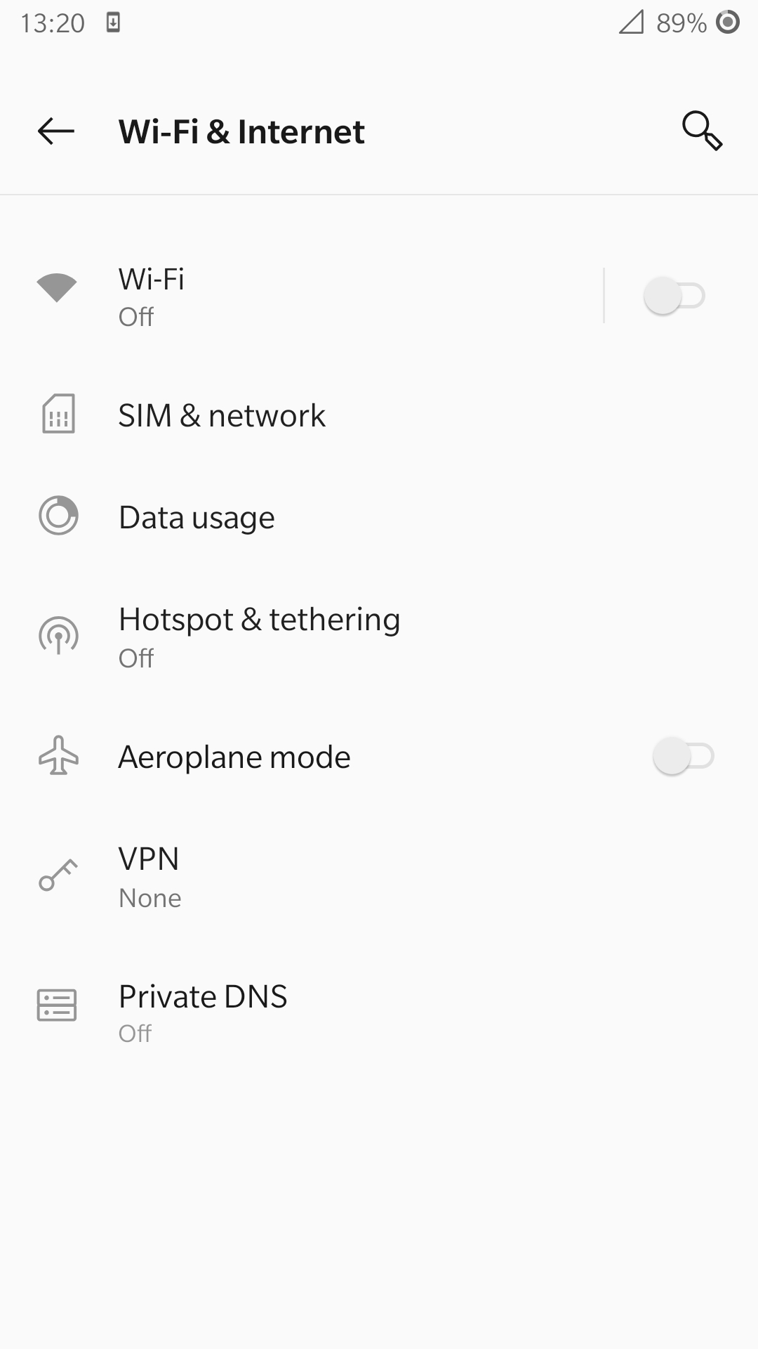
Open this menu and proceed to the sub-menu associated with the USIM being used. It should look something like the following:
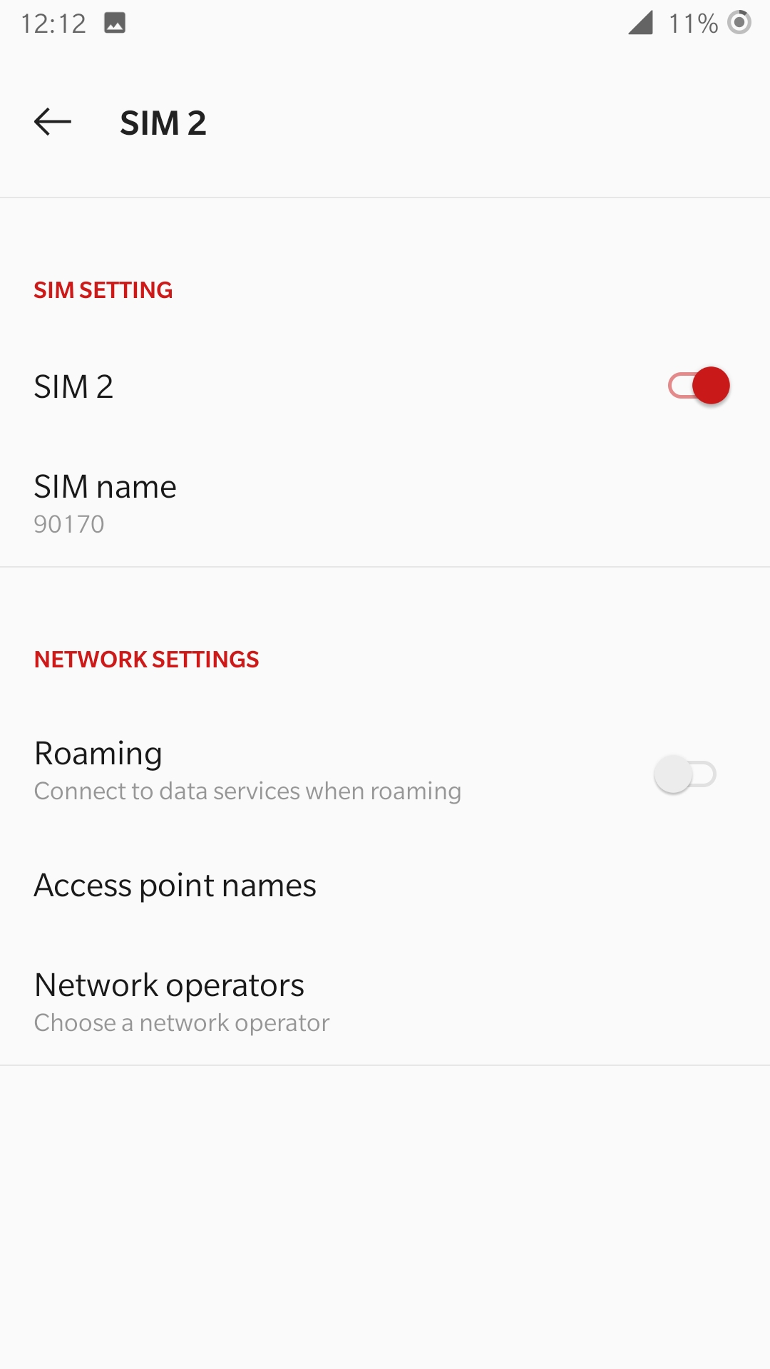
Under the Network Operators find the network which you have just instantiated using srsRAN 4G.
Select the network that is a combination of your MMC & MNC values. The UE should then automatically connect to the network.
Confirming connection
Once the UE has connected to the network, the console outputs of the srsENB and srsEPC can be used to confirm a successful connection.
srsENB
If a successful connection is made, a RACH message should be seen followed by a USER <ID> connected message where “<ID>” is the RNTI assigned to the UE:
==== eNodeB started ===
Type <t> to view trace
Setting frequency: DL=806.0 Mhz, UL=847.0 MHz for cc_idx=0 nof_prb=50
Setting frequency: DL=1842.5 Mhz, UL=1747.5 MHz for cc_idx=1 nof_prb=52
User 0x46 connected
RACH:  slot=7691, cc=0, preamble=41, offset=1, temp_crnti=0x4602

          -----------------DL----------------|-------------------------UL-------------------------
lte   46   12   0    5   2.5k    4    0   0% |  25.7    9.4   23   23    17k    4    0   0%    0.0
 nr 4601  n/a   0    0      0    0    0   0% |   n/a    n/a    0    0    38k    4    0   0%    0.0
lte   46   13   0    0      0    0    0   0% |   n/a    6.2    0    0      0    0    0   0%    0.0
 nr 4601  n/a   0    0      0    0    0   0% |   n/a    n/a    0    0      0    0    0   0%    0.0
lte   46   13   0    0      0    0    0   0% |   n/a    6.2    0    0      0    0    0   0%    0.0
The UE is now connected to the network and should now automatically connect to this network each time it is powered on. The UE should now also have access to the internet - as if connected to a commercial 5G network.
Troubleshooting
UE not attaching to network
Some UEs have issues detecting networks operating on a test PLMN such as 00101. Using the MCC of your local country can increase the chance to find the network. When using a shielded environment, better results may be seen when using the PLMN of a local commercial network.
Warning
To avoid causing interference to local commercial networks, carry out tests using a shielded environment.
NR carrier has high error rate
One of the current limitation of the NR scheduler is missing dynamic MCS adaptation. Therefore, a fixed MCS is used for both downlink (PDSCH) and uplink (PUSCH) transmissions. By default we use the maximum value of MCS 28 for maximum rate. Depending on the RF condiditions this, however, may be too high. In this case, try to use a lower MCS, e.g.:
[scheduler]
nr_pdsch_mcs = 10
nr_pusch_mcs = 10
Ettus Research USRP N310
The N310 is another device that can be used for NSA. However, a few changes need to be made to the configuration files.
In the enb.conf we need to change the device arguments to pick the right RF subdevice (band 20 for LTE and band n3 for NR are too far apart to use the default) and also use sample rates supported by the N310:
[rf]
device_args = type=n3xx,tx_subdev_spec=A:0 B:0,rx_subdev_spec=A:0 B:0

[expert]
lte_sample_rates = true
The tests have been made with the N310 using UHD 4.1.